Table of Contents
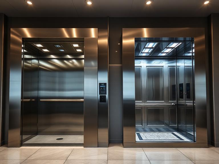
Architectural Blueprint & Engineering Guide for Elevator Installation in Kukatpally
Managing vertical engineering projects within Kukatpally’s high-density real estate corridors requires a clear framework for capital planning. Whether you are upgrading older residential buildings in KPHB Colony, managing mixed-use commercial developments along the JNTU-Kukatpally main road, or building premium multi-floor luxury villas in Pragathi Nagar and Nizampet, selecting and setting up vertical transit assets is a highly critical structural investment.
In the current 2026 real estate landscape, elevator installation in Kukatpally involves much more than just purchasing mechanical hardware. The process requires careful civil-mechanical alignment, upgrading electrical infrastructure, and complying with the mandatory safety and inspection standards enforced under the Telangana Lifts Act.
This comprehensive technical procurement framework details current market pricing, architectural structural requirements, specialized drive options, step-by-step engineering workflows, and statutory compliance protocols for project developers, housing societies, and property managers.
1. Capital Cost Framework for Elevator Installation (2026 Procurement Baseline)
The financial requirements for an elevator installation depend heavily on your building’s height, the chosen drive technology, weight capacity, and cabin finishes. The table below outlines the current capital cost framework for completely setting up an elevator system in the Kukatpally area:
Comprehensive Pricing & Engineering Baseline Matrix
| Building Layout & Operational Profile | Core Drive Technology | Door Configuration & Control System | Estimated Turnkey Investment (INR) | Civil & Structural Overhead (INR) | Total Projected Cost (INR) |
| G+1 Duplex / Luxury Villa (3-4 Passenger Capacity) | Compact Pneumatic / Pitless Hydraulic | Manual Swing Glass / Automatic Telescopic | ₹8,50,000 – ₹11,00,000 | ₹1,50,000 – ₹2,50,000 | ₹10,00,000 – ₹13,50,000 |
| G+3 Standalone Independent Home (4-6 Passenger Capacity) | Standard Geared Traction Drive | Manual Collapsible Mesh / Auto Sliding | ₹9,00,000 – ₹12,50,000 | ₹2,00,000 – ₹3,00,000 | ₹11,00,000 – ₹15,50,000 |
| G+4 Residential Builder Floor (6 Passenger Capacity) | Machine Roomless (MRL) Gearless | Microprocessor-Driven Automatic Sliding | ₹12,50,000 – ₹16,00,000 | ₹2,50,000 – ₹3,50,000 | ₹15,00,000 – ₹19,50,000 |
| G+5 High-Density Apartment Complex (8 Passenger Capacity) | High-Speed Permanent Magnet Gearless | Full Automatic Center-Opening SS 304 | ₹14,50,000 – ₹19,00,000 | ₹3,00,000 – ₹4,50,000 | ₹17,50,000 – ₹23,50,000 |
| G+10 Commercial / Mixed-Use Hub (13-15 Passenger Capacity) | Variable Frequency (VVVF) High-Speed Gearless | Fire-Rated Heavy Duty Automatic Sliding | ₹18,00,000 – ₹24,00,000 | ₹3,50,000 – ₹5,50,000 | ₹21,50,000 – ₹29,50,000 |
2. Technical Evaluation of Drive Technologies
Choosing the right drive technology is a foundational engineering decision that directly impacts your building’s structural design, long-term power usage, and future maintenance costs.
A. Machine Roomless (MRL) Gearless Traction Drives
MRL gearless traction configurations are the primary industry choice for new residential and commercial structures over three stories high.
- Mechanical Mechanism: These systems utilize a high-torque, synchronous permanent magnet motor mounted directly inside the top of the elevator hoistway, completely eliminating the need for a separate rooftop machine room.
- Energy Consumption: They operate with high electrical efficiency, reducing energy use by up to 40% compared to traditional geared setups.
- Long-Term Performance: By removing the worm-and-gear transmission block, the system minimizes mechanical wear, lowers long-term maintenance costs, and eliminates the risk of oil leaks.
B. Hydraulic Actuation Systems
Hydraulic drive systems are well-suited for low-rise homes (G+1 or G+2) where overhead roof clearance is restricted or adding a traditional heavy masonry shaft is structurally impractical.
- Mechanical Mechanism: The elevator cabin is raised and lowered by an oil-driven hydraulic piston assembly powered by a compact pump unit that can be placed up to 10 meters away from the shaft.
- Structural Benefits: The structural loads are directed downward into the foundation floor pit, reducing the stress placed on the upper building walls.
- Limitations: They are typically restricted to lower travel speeds and have a maximum vertical travel height of around 15 meters.
C. Pneumatic Vacuum Systems
Pneumatic or vacuum elevators are highly popular options for retrofitting existing multi-floor homes and luxury duplexes across modern residential neighborhoods.
- Mechanical Mechanism: The system controls air pressure within a sealed, transparent cylindrical tube structure, using a vacuum turbine system to pull the cabin upward and smoothly releasing air pressure to let it descend.
- Spatial Benefits: These designs are self-supporting and require no structural pit, counterweights, or rooftop machine rooms. They can be installed quickly, often in just 2 to 4 working days, directly onto finished interior floors.
3. Structural & Civil Engineering Specifications
For an elevator installation to operate safely and reliably, the building’s shaft must be constructed to exact, sub-millimeter specifications. Any structural alignment errors can cause permanent ride vibration, accelerate wear on guide rails, and fail safety audits during inspection.
Critical Structural Parameters
1. Shaft Verticality and Alignment (Plumb Line Tolerances)
The interior walls of the elevator shaft must be perfectly vertical. For a standard G+5 building, the total deviation from a true vertical plumb line from the roof down to the pit floor must not exceed +5mm. If the shaft walls slant or twist, the guide rails cannot be mounted evenly, which creates operational friction and triggers safety shutdowns.
2. Base Foundation Sub-Structure (Elevator Pit Specs)
The concrete pit at the base of the shaft must absorb significant operational forces and hold emergency buffer springs.
- Pit Depth: A standard traction elevator requires a minimum pit depth between 1200mm and 1500mm.
- Waterproofing: The base and walls of the pit must be fully waterproofed using professional chemical injection or crystalline membranes to prevent underground water seepage from damaging the lower limit switches, steel cables, and structural anchors.
- Sump Systems: In areas prone to high water tables, engineers should install a dedicated corner drainage sump to keep the base of the shaft dry.
3. Overhead Clearance and Machine Roomless Slab Strength
The clear vertical distance from the top landing floor to the underside of the hoistway roof slab must measure at least 4200mm to 4500mm. This overhead space protects maintenance technicians during service work and prevents the car from striking the roof structure during an unintended over-travel situation. The upper structural slab must be cast using durable M25 grade concrete to securely support the heavy weight of the primary drive motor.
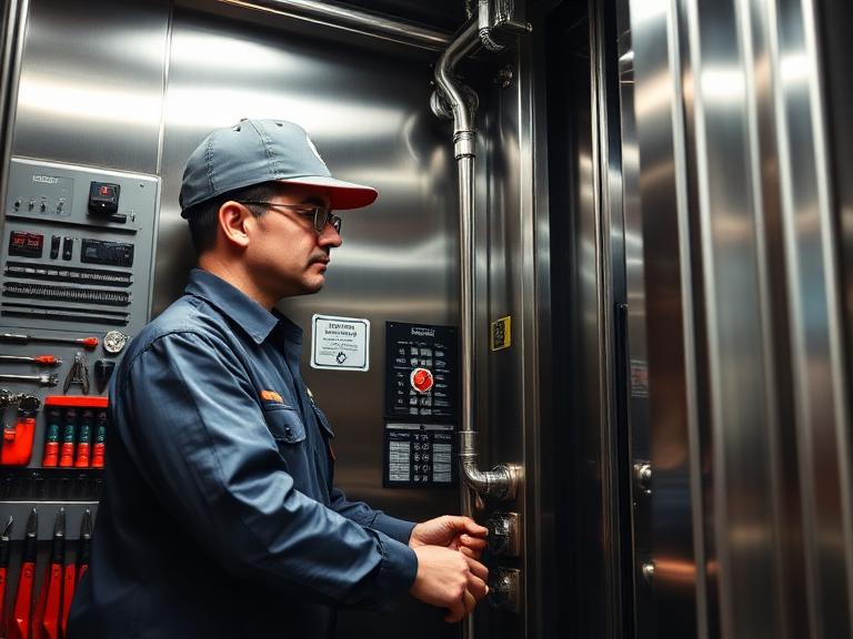
4. Operational Step-by-Step Installation Workflow
Installing an elevator system requires a highly organized, step-by-step mechanical and electrical engineering process to ensure long-term reliability.
Turnkey Installation Phases
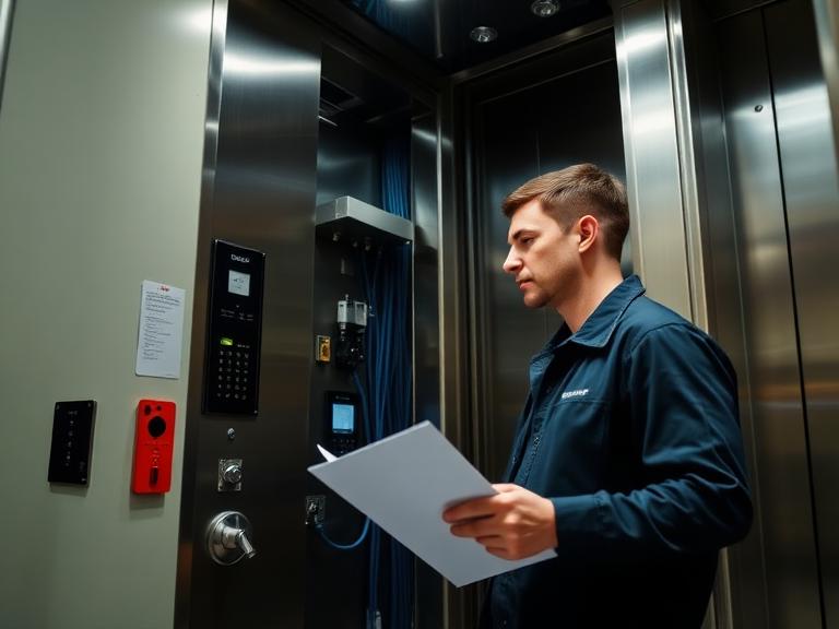
1.Initial Site Structural Audit and Engineering Verification:Phase 1.
The engineering team uses precise digital laser measures to verify the shaft’s dimensions, internal vertical plumb alignment, overhead clearance heights, and pit depths against approved factory blueprints before unboxing any machinery components.
2.Structural Bracket Anchoring and Guide Rail Erection:Phase 2.
Technicians mount heavy steel support brackets into the shaft walls at precise vertical intervals of 1.5 to 2.0 meters. The main cabin and counterweight guide rails are bolted into place and aligned using high-accuracy dial indicators to prevent any operational vibration.
3.Drive Machinery Placement and Suspension Wire Re-Roping:Phase 3.
The permanent magnet gearless motor assembly is anchored at the top of the hoistway or within a dedicated machine room. High-tensile steel wire ropes or coated steel belts are threaded over the drive sheave to connect the cabin frame directly to the counterweight block.
4.Cabin Assembly, Interlocking Doors, and Electrical Integration:Phase 4.
The main cabin enclosure is assembled inside the lower section of the shaft. Structural door frames and automatic landing doors are set up at each floor level. Technicians route the main traveling electrical cables and connect the central microprocessor control panel to the building’s main power supply.
5.Static Weight Load Calibration and Safety Commissioning:Phase 5.
The completed system undergoes full performance validation testing. Engineers place physical test weights inside the cabin to verify the emergency braking systems, test the speed governor, check the Automatic Rescue Device (ARD) functionality, and complete the installation.
5. Safety Compliance: The Telangana Lifts Act and NBC 2016 Standards
Operating a passenger elevator carries a high level of public safety responsibility. Every new elevator installation must follow the strict legal frameworks enforced by local regulatory authorities.
Mandatory System Protections
- Automatic Rescue Device (ARD): The National Building Code 2016 mandates that every passenger lift feature an independent, battery-powered ARD system. If the building loses main utility power, the ARD must automatically engage within 10 to 15 seconds, move the cabin smoothly to the nearest available floor landing, and open the sliding doors to let passengers exit safely.
- Infrared Light Curtain Protection: Traditional, mechanical safety edges are no longer acceptable for modern automatic doors. New installations must include a multi-beam electronic infrared light curtain. This sensor system projects a continuous matrix of invisible light beams across the doorway, instantly reopening the doors if any obstruction is detected without making physical contact with passengers.
- Overload Protection Monitoring (OLPD): Lift cabins require built-in strain gauges or under-platform load cell sensors. If the cabin weight exceeds its rated operational capacity, the OLPD system must trigger an audible warning buzzer, illuminate a visual indicator, and lock the control logic to prevent the lift from moving until the excess weight is removed.
6. Frequently Asked Questions (FAQs)
Q1: Can an elevator be installed in an older, existing residential building that wasn’t built with a lift shaft?
A: Yes, elevators can be retrofitted into existing multi-floor buildings. If there is no internal space available to cut through concrete floors, engineers can build an external self-supporting structural steel or masonry tower shaft against an outer wall. Once the structural tower is complete, window or wall sections are opened at each floor landing to create access doors for the new elevator cabin.
Q2: What are the primary electrical power requirements for a modern G+4 apartment elevator installation?
A: A standard 6 to 8 passenger traction elevator requires a dedicated 3-Phase, 415V, 50Hz electrical supply connected to an independent circuit breaker in the building’s main utility room. The power line should feature a high-quality voltage stabilizer and a surge protection device to protect the elevator’s sensitive variable frequency drive inverter components from sudden voltage fluctuations or spikes.
Q3: How long does the complete on-site process take for an elevator installation?
A: For a standard G+4 or G+5 residential building with a pre-constructed, properly aligned masonry shaft, the mechanical erection, electrical wiring, and safety calibration phases typically take 4 to 6 weeks to finish. This timeline may extend if the project requires complex custom civil modifications, deep structural waterproofing, or extensive external structural steel tower construction.
Q4: Why are machine roomless (MRL) gearless systems priced higher than traditional geared traction options?
A: MRL gearless systems use a more advanced design that features high-torque, synchronous permanent magnet motors and sophisticated microprocessor controls. While the upfront equipment cost is higher, they eliminate the need to construct a dedicated concrete rooftop machine room, save space, use less electricity, and require far fewer long-term maintenance visits, making them more cost-effective over the life of the building.
Q5: Who is responsible for managing and obtaining the official operational license required by the state government?
A: The licensed elevator installation company generally prepares the technical design drawings and handles the paperwork for the Telangana State Electrical Inspectorate application process. Once the physical installation is complete, an official state inspector visits the site to audit the safety systems, test the emergency brakes, and check the ARD functionality before issuing the final legal operating license to the building society or property owner.